This page is intended to guide you through the installation and handling of our products. Please note that a little attention to detail may help you avoid malfunctions or repairs.
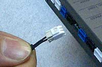
When disconnecting the connector from the control unit or meter, carefully pull it out while securely pressing the lock. Forcibly pulling on the connector without pressing the connector lock may cause the control unit or meter connector to disconnect or the connector to be damaged. If the connector on the wire side is damaged or disconnected, it cannot be repaired and the wire must be replaced with a repair part.
Also, pulling only on the wire part without holding the connector part may cause the sheath to come off or the wire to be disconnected. If the sheath comes off, the core wires may short-circuit each other, the vehicle’s fuse may blow, and the control unit or meter circuit may be damaged. Be very careful not to pull or drop the product while the wire is connected.
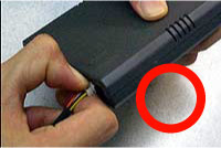
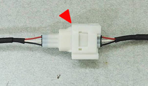
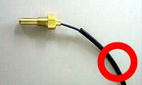
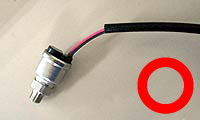
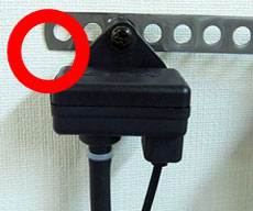
When unplugging the connector, press firmly on the connector lock as shown in the picture.
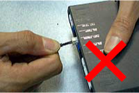
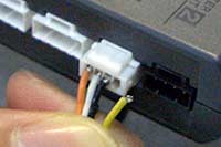
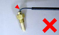
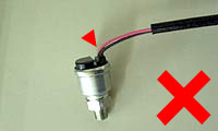
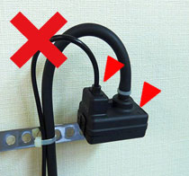
Do not pull on the wire part without pressing the lock on the connector.
If the wire part is pulled without pressing the lock on the connector, the meter and the connector on the unit side will come off together.
Pulling on the wire part of the connector will cause the wire to break or the coating to peel off.

Pulling on the unit or wire while it is connected may break the wire.
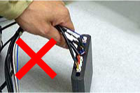
If the wire is left connected and dangling, there is a risk of wire breakage.
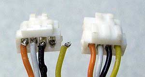
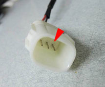
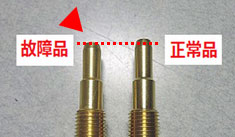
The connector on the right side is in normal condition. On the left side, the yellow wire is broken due to pulling or twisting of the wire part. The other three wires have also had their coatings peeled off, revealing the core wires.
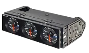
When adding a gauge, it is often necessary to disconnect the existing gauges and control unit. When disconnecting, be careful not to pull on the connected wire. Also, the connector locks tightly, so press firmly. If core wires are visible, replace the wire promptly.
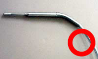
When wiring, do not bend the harness at the sensor section and pull it straight out. Be very careful with the wiring and secure it with slack.
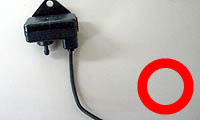
The image below shows a water temperature sensor being installed. When installing other sensors, please handle them with the same care.
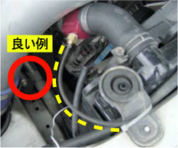
○Good Example :
No stress on the base of the wire due to slack in the sensor
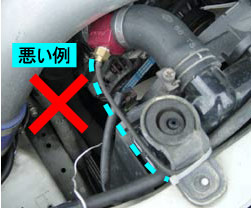
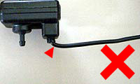
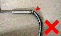
×Bad Example : Stress on the base of the wire due to not slack in the sensor
○ in the following pictures means GOOD and × means BAD.
As shown in the photo below, if the water temperature sensor is attached to a silicone upper hose, the temperature may be displayed lower because the tip of the sensor is not contact with the coolant flow path.
For installation of Therefore, use one of the following methods for installation.
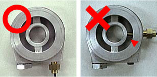
When installing the temperature sensor to the sensor attachment, make sure that the tip of the sensor does not touch the center bolt of the attachment.
If the sensor tip is hit against the center bolt, the sensor tip will be crushed, causing failure of the internal temperature sensor or thermistor abnormality.
Defi recommends using a commercially available sensor attachment between the engine and oil filter to install the oil temperature sensor. However, in many cases, the oil temperature sensor is installed in the drain bolt section of the oil pan. If the sensor is installed in the drain bolt area, the wire part of the sensor may be twisted when the oil temperature sensor is removed for oil change, and the wire may be disconnected. Therefore, please install the oil temperature sensor in the recommended way we mention.
*Please purchase the appropriate sensor attachment for the sensor to be installed on the drain bolt section.
・Sensor thread pitch: 1/8PT
・Diameter of tip: 7mm
For sensor specifications, please click hereSensor specification
When installing the oil temperature sensor on the drain bolt, be sure to connect the sensor and sensor wire connector last. If the connector is connected first, the wire will be twisted when the sensor is attached to the bolt.
When changing the oil, install the oil temperature sensor in accordance with the procedure described in “To all users who have installed an oil temperature sensor” below. The installer should also ask the user to follow these steps to change the oil
Please inform the vendor or store operator to follow the procedure below when changing the oil.
*Never remove the sensor from the sensor attachment.
*Be careful not to twist the wire part of the sensor.
*When disconnecting the connector, do not pull on the wire part, but press firmly on the lock and pull on the connector part.
For Subaru vehicles with horizontally opposed engines
If the oil pressure sensor is installed close to the oil pump, the pressure pulsation may increase and momentarily exceed three times the full scale. In such cases, the sensor may be adversely affected. Therefore, the oil pressure sensor should be installed by removing the oil element and using a sandwich-type attachment that is placed between the oil filter.
For Daihatsu vehicles with 4-cylinder engine (JB-DET engine) (All Copen, Move, MAX, and Opti models)
If the oil pressure sensor is installed directly to the pressure switch mounting area of the engine, the pressure pulsation may increase and momentarily exceed three times the full scale. In such cases, the sensor may be adversely affected. Therefore, Therefore, please install the sensor in one of the following ways:
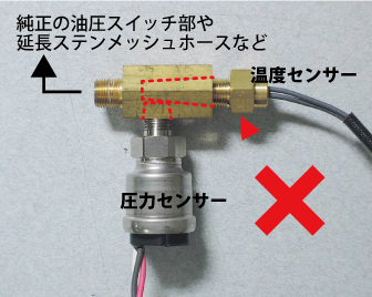
Do not use an adapter that splits the oil pressure switch section of the vehicle stock.
・When an oil temperature sensor is used, the temperature may be displayed low because the sensor sensing part does not contact the flowing part of the oil.
・The tip of the oil pressure sensor may contact the oil temperature sensor, which may cause the oil temperature sensor to malfunction or fail to display normal oil pressure.
Install the turbo sensor so that the side with the wires coming out is down. If the turbo sensor is installed with the side with the wires coming out on top (see picture on the right), water can easily enter at the base of the wiring wire or through the atmospheric pressure inlet, and the turbo sensor may fail in a short period of time.
When fixing the sensor wire, wire it in a location where it will not be exposed to water. If wiring is done in a location that is constantly exposed to water, such as around a radiator, water can easily get inside the connector, and the terminals inside the connector may corrode in a short period of time. In such cases, the sensor will be damaged and correct readings will not be displayed.